
AtoVproject - lx-euclid - DIY kit - V1.1
Check the version number of your kit! The hardware revision is labelled on the box and the PCB. This manual is for assembly of Version V1.1. If you have Version V1.0, please click here to access the corresponding manual.
Introduction
Thank you very much for purchasing one of our DIY kits.
This manual is aimed at guiding you step by step through the process of assembling an AtoVproject lx-euclid. If you have any questions or if you are missing a part please contact us at Support@atovproject.de.
Although the LEDs are color-coded, the kit is designed to be color-blind friendly (except maybe those with achromatopsia), making it easy for anyone to assemble.
Required tools and materials
First, to successfully build this DIY kit, you will need a few tools and materials.
Soldering Iron
No need for a high-end iron. Temperature control is preferable to avoid burning the flux in your solder and leaving residues. With prolonged use, higher than necessary temperatures will damage your soldering iron tip. We recommend the TS-100 or TS-80 digital soldering irons for hobbist use. As professional tools we use the JBC CD-2BQF with a range of tips.
Solder
We recommend lead-free solder as it is gentler on the environment and your health.
We have tested a lot of solder over the years and we now recommend the Stannol Kristall 611 TSC - Sn96.5Ag3Cu0.5. For a good all-rounder we would recommend 0.7 mm diameter solder. This is a truly no-clean solder; leaving very little residue, a great finish and with odorless flux fumes. (They do not sponsor us, we just very much like their product and we use them in our production line -Bonus- Their customer service is great!)
Side cutter
We like flush cutters but side cutters will also work. Any cheap cutters will do but higher quality tools will last longer. Knipex is our go to in the workshop
Multimeter
This is important to have for testing and troubleshooting. Use a multimeter with continuity mode. Our reliable and inexpensive multimeter recommendation is the ANENG AN8009. If you are in the market for a professional tool, we use the Brymen BM867s (or BM869s if you need temperature probing)
Flux (optional but recommended)
Liquid no-clean flux is sufficient for such a build. In our workshop we use Stannol 32-10/i no-clean flux pen.
Oscilloscope (optional, could be a good investment if you want to get serious into electronics)
We use the Siglent SDS1104X-E which has been fulfilling our needs until now. Unfortunately, we don't have experience with cheaper oscilloscopes. But I would recommend getting a digital one instead of analog as they have measuring tools, memory, take snapshots, can decode digital signals etc… Good oscilloscopes are expensive and this one is a great budget option.
Secondly, to build this kit you need to know how to solder. If you want to learn how to solder, our recommendation is to purchase an inexpensive DIY kit from your local electronics shop. This will allow you to train yourself at soldering and build confidence before building a more complex kit.
If you need a small refresh on soldering techniques, here is a tutorial https://www.youtube.com/watch?v=Qps9woUGkvI
Opening the kit
The kit should contain:
1 x Aluminium panel
1 x PCB populated with SMD components
1 x Touchplate PCB
1 x bag of parts
1 x 3d printed plastic ring
1 x Eurorack power cable
Open the bag lx-euclid Parts. Make sure this bag contains the following.
5 x M3 screws
10 x jacks + nuts
6 x LED buttons
1 x 90° 2*5 header
2 x 90° 3 pin header
1 x THT 2*6 socket
1 x flat flex cable 5 cm
1 yellow LED
1 Red LED
1 Blue LED
1 Turquoise LED
Check if the kit is complete as well the state of the provided parts. We inspect inspect everything in the workshop but it's possible that damages occur during shipping. If there are any obvious defect on any of the parts provided please contact us, we will provide a replacement.
Part 1 - Through hole parts on main board
1 - Vertical Header
The first step is to solder the 2*6 header socket. The header goes on the top side of the PCB where all the SMD parts are soldered. Place the part on its footprint and solder only one pin. Then turn the PCB around and make sure that the header sits flush against the PCB. If not, reheat the pin with your iron and push the header in place with a finger.
Once placed well and straight solder the rest of the pins.


2 - THT 90° Headers

Place the two 3 pin headers and the boxed 2*5 header on their corresponding locations.
The trick here to to secure the header by soldering one pin from the top side of the PCB and reheat the same pad to correct the position of these header by pressing on them with your finger. Finally turn the PCB around and solder the rest of the pins on the back side of the PCB
2 - Display
Preparing the display
First thing to do is to remove the tape that is on the threaded standoffs.


Connect the display to the main board
The display is connected to the main board using a 5cm flat flex cable. First start by inserting the cable into the connector of on the display assembly itself. To do so you need to use a pair of tweezers. Open the connector with the tweezers. Bend the blue section of the cable at a 90 degree angle. Insert the cable into the connector using the tweezers and close the connector to secure the cable in place.


Once this is accomplished you can connect the cable to the main board in same way. Make sure the cable is connected the right way around with the blue section up. See the picture :

Finally, secure the display in place using four M3 screws.

3 - Interface components
First start by placing the led switches. Please note that these are polarized. There is a painted mark on one of the pins. These pins go on the right.


Then proceed to place the rest of of the parts.
It can help to prop up the module a little so the legs of the LEDs have somewhere to go. A roll of tape for example does the trick nicely.
Note about the LEDs:
The LEDs are polarized and the long leg goes to the left where the + sign is.
Despite the fact that the LEDs are colour coded, we tried to make the kit colour blind friendly by using LEDs with different length of legs.
From left to right the LEDs colours are Yellow (long legs), Red (short leg), Blue (Short legs), Turquoise (Long legs)

It is now time to remove the protective film of the display.


4 - Place the panel
Before mounting the panel on the parts. Start by placing the provided plastic ring on the back side of the panel. Then place the panel while holding the ring in place.
After placing the panel, ensure the ring is properly positioned before securing it. Misalignment could put pressure on the display and potentially damage it.
Finally, secure the panel using the last M3 screw and a nut on one of the jacks.


Turn the module around and solder just one pin of the jack where you’ve placed a nut. Then, reheat the pad and press the jack to ensure it sits flush against the board.
Next, adjust the LEDs to fit properly into their panel holes, then proceed to solder the remaining components.
Touchpad installation
Connect the touchpad to the main board, ensuring the connectors are properly aligned. Push the touchpads all the way in. The plastic ring has a small lip designed to help center the pads on the module. You may need to adjust the pads slightly for proper alignment.
For factory-assembled modules, we use cyanoacrylate (superglue) to secure the touchpads to the panels. If you choose to do the same, use only a very small amount, as excess glue can damage the panel.
Part 2 - Firmware upload and testing
Firmware upload :
Download the Firmware
Download the latest firmware on the GitHub project page.
Latest: Stable and official release.
Pre-release: Unstable, in development, with upcoming features.
Connect to Your Computer
Use a USB-C cable to connect the LX-Euclid to your computer.
Detect the LX-Euclid
If no firmware has ever been loaded, the LX-Euclid will appear as a storage device named RPI-RP2.
If that’s not case you’d need to enter the USB Boot Mode
Press and hold the USB BOOT button.
Tap the RST button and release USB BOOT. Both buttons are located on the edge of the PCB.
The LX-Euclid should now appear as a storage device named RPI-RP2.
Upload the Firmware
Drag and drop the downloaded firmware file into the RPI-RP2 storage device.
Install the Module
Once the firmware is uploaded, place the module back in your system.
This process will upload the firmware to your LX-Euclid module.
Testing
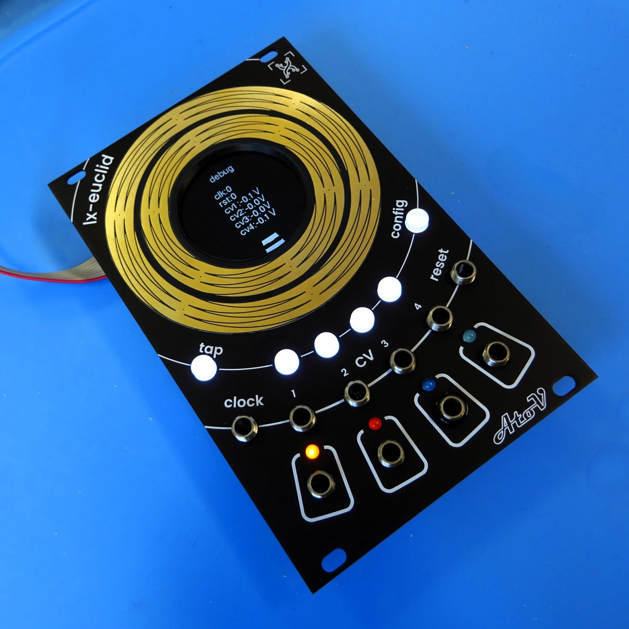
Power Up in Debug Mode
Connect the LX-Euclid to a Eurorack power supply.
Turn on your system while holding down both the Tap and Config buttons.
The module will boot into debug mode, allowing you to check if everything is functioning correctly.
Testing the Rings, LEDs and buttons
Run your finger around both rings and ensure that the indicators follow your finger all the way around.
Check the LEDs to confirm they light up in sync with the rhythm.
Ensure that all buttons are lit up.
Press each button and check if the LED for the corresponding button turns off.
Check CV Inputs
Send CV signals to each of the CV inputs and monitor if the voltages are being read correctly. Please note that the converters are not calibrated so some difference between the reading and the actual voltage sent to the module is to be expected.
Check Gate Inputs
Send gate signals to the Clock and Reset inputs to verify that the signals are being detected properly.
Test Outputs
Connect each output of the LX-Euclid to a device that responds to gate signals and check that all outputs are functioning correctly.
These steps will help you ensure that your module is working as intended.
Any issues? Contact us at Support@atovproject.de
Part 3 - Final assembly
When everything works well, then you can finally install the remaining jack nuts and install your module in your system for you to enjoy!
