
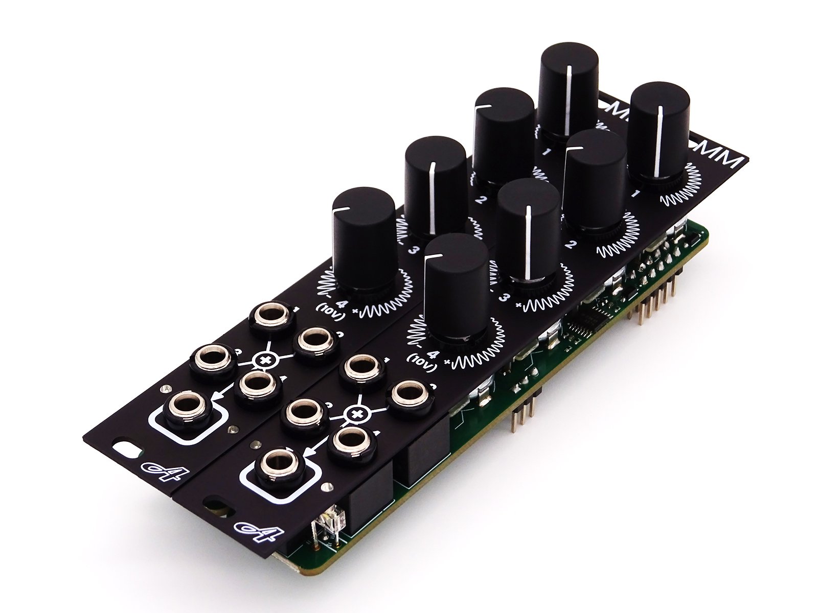
AtoVproject MMx2 - DIY kit

Introduction
Thank you very much for purchasing one of our DIY kits.
This manual is aimed at guiding you step by step through the process of assembling an AtoVproject cDVCA. If you have any questions or if you are missing a part please contact us at Support@atovproject.de.
Required tools and materials
First, to successfully build this DIY kit, you will need a few tools and materials.
Soldering Iron
No need for a high-end iron. Temperature control is preferable to avoid burning the flux in your solder and leaving residues. With prolonged use, higher than necessary temperatures will damage your soldering iron tip. We recommend the TS-100 or TS-80 digital soldering irons for hobbist use. As professional tools we use the JBC CD-2BQF with a range of tips.
Solder
We recommend lead-free solder as it is gentler on the environment and your health.
We have tested a lot of solder over the years and we now recommend the Stannol Kristall 611 TSC - Sn96.5Ag3Cu0.5. For a good all-rounder we would recommend 0.7 mm diameter solder. This is a truly no-clean solder; leaving very little residue, a great finish and with odorless flux fumes. (They do not sponsor us, we just very much like their product and we use them in our production line -Bonus- Their customer service is great!)
Side cutter
We like flush cutters but side cutters will also work. Any cheap cutters will do but higher quality tools will last longer. Knipex is our go to in the workshop
Multimeter
This is important to have for testing and troubleshooting. Use a multimeter with continuity mode. Our reliable and inexpensive multimeter recommendation is the ANENG AN8009. If you are in the market for a professional tool, we use the Brymen BM867s (or BM869s if you need temperature probing)
Flux (optional but recommended)
Liquid no-clean flux is sufficient for such a build. In our workshop we use Stannol 32-10/i no-clean flux pen.
Oscilloscope (optional, could be a good investment if you want to get serious into electronics)
We use the Siglent SDS1104X-E which has been fulfilling our needs until now. Unfortunately, we don't have experience with cheaper oscilloscopes. But I would recommend getting a digital one instead of analog as they have measuring tools, memory, take snapshots, can decode digital signals etc… Good oscilloscopes are expensive and this one is a great budget option.
Secondly, to build this kit you need to know how to solder. If you want to learn how to solder, our recommendation is to purchase an inexpensive DIY kit from your local electronics shop. This will allow you to train yourself at soldering and build confidence before building a more complex kit.
If you need a small refresh on soldering techniques, here is a tutorial https://www.youtube.com/watch?v=Qps9woUGkvI
Opening the kit
The kit should contain:
2 x panel
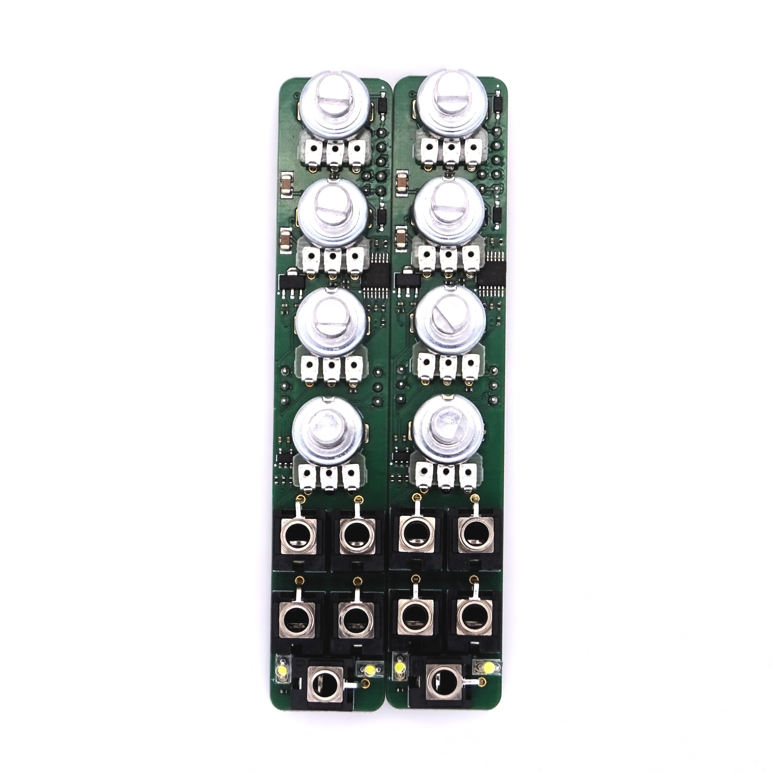
2 x PCB populated with SMD components
2 x bag of parts
8 x knobs
2 x Eurorack power cable
2 x 3pin dupont cable
Open the bags MM Parts. Make sure each bag contain the following.
4 x potentiometer + nuts
5 x jacks + nuts
2 x LEDs
1 x 2*5 pin header
2 x 3pin header
Check if the kit is complete as well the state of the provided parts. We inspect inspect everything in the workshop but it's possible that damages occur during shipping. If there are any obvious defect on any of the parts provided please contact us, we will provide a replacement.
Part 1 - Back Side
There is only three part to solder on the back of the PCB, the 2*5 pin header used a Eurorack power connector and two 3 pin headers.


Put the connectors in their locations and solder one pin on each. I would recommend soldering a pin in a corner of the power connector. The central pins are connected to ground and because of the internal ground plane take a more heat to solder.
When this is done, check if the connector is flush against the PCBs. If this is not the case. Reheat the pin you previously soldered and push the connector down with your finger. Remove the iron and let the solder resolidify.
When everything looks good, proceed then to solder the rest of the pins.


Part 2 - Front Side
Start by placing the 4 potentiometers. These are “snap in” they will therefore snap in place and hold on the PCB. Make sure they are pushed all the way against the PCB. Once done, you can proceed to place the 5 jacks and the LEDs.

Place the front panel and use a nut on one of the potentiometer to secure it in place. Then place some tape on the LED holes (painters tape works great because it is designed not to leave traces). Push the LEDs into their holes and against the tape. This will hold them in place.

Then you can flip the module around and solder the components.


Testing
Start by chaining the two modules.
To chain two modules, connect the provided 3-pin cable from the OUT header of the first MM to the IN header of the second MM. Each wire of the cable has a different color; make sure to match the colors on the top of both sides.
Connect both modules to your Eurorack power supply.
The LEDs indicate the signal levels at the output of the module.
Operate the 4th potentiometer and look at the LEDs when turned to the right the right LED should light up and to the left the left LED should light up. Perform this operation on both MM modules. If successful place the potentiometer in its center position where both LEDs are off.
Connect a unipolar (constant CV, envelope etc…) signal to channel 1 of the leader MM.
Attenuate this signal with the first potentiometer. You can monitor the activity with the LEDs. Only the right LED should light up. Without disconnecting the signal from the first module perform the same operation on the second MM, the same results should occure.
Test channel 2 in the same maner.
Then connect the same CV into channel 3. This channel is equipped with an attenuverter so by turning this control to the left the signal should be inverted and the left LED should light up. Same thing on the second module.
Any issues? Contact us at Support@atovproject.de
Part 4 - Final assembly
When everything works well, then you can finally install the remaining jack and pot nuts. Put the push on knobs onto the potentiometers.
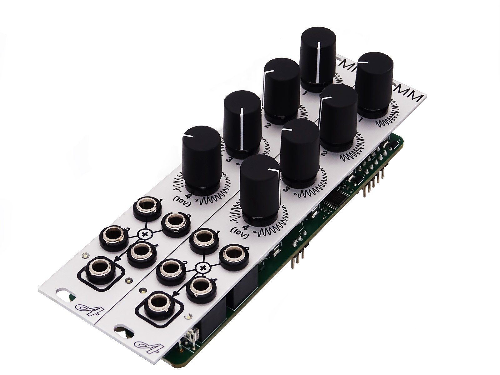
Congratulations! Your AtoVproject MMx2 is now complete and fully functional!