
AtoVproject cDVCA - User Manual
Introduction
cDVCA or class-D VCA is a new kind of VCA based on an entirely novel concept that is inspired from class-D amplification technology. This is not a transparent VCA and brings a lot of character to the sound with its waveshaping abilities.
How does it work
The cDVCA is inspired by class D amplification. In this technique, an ultrasonic internal triangle oscillator is compared to the input signal. This encodes the signal into a PWM signal. The signal is then filtered using a low pass filter to recover an analog signal. It is

Representation of the signal path of a classical class D amplifier.
For the uninitiated, a PWM signal (Pulse width modulated signal) is a type of digital encoding for analogue signal. Another name for it is pulse-duration modulation (PDM). The analogue value is encoded by the duty cycle, that it the proportion of time up or down (100% being fully on and 0% being fully off).
When comparing an analogue signal to a higher frequency. The resulting digital signal will be high when the input signal is higher than the reference wave and low when it is lower. That is the analog method to encode a signal into a digital PWM. In this case digital means zero and ones, no programmable hardware is involved as the cDVCA is an entirely analog module.
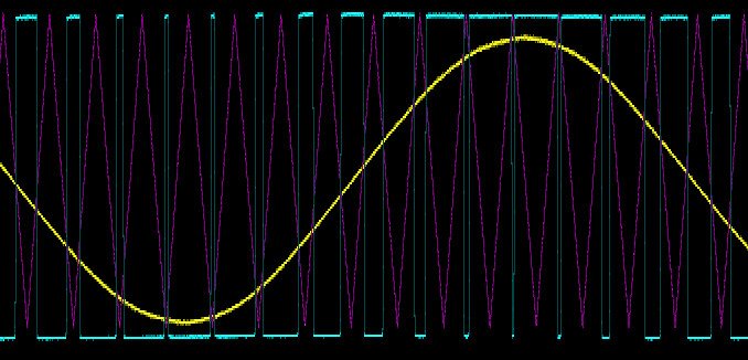
Oscilloscope recording of the class D encoding. The yellow trace is the input signal, the purple trace is the carrier triangle oscillator and the blue trace is the resulting PWM signal.
Contrary to classic class D technique, the frequency of the carrier oscillator is variable and can be turned down into the audio range to create interesting waveshaping. The oscillator is also controllable by CV and tracks 1V/oct, this allows for the timbre to remain constant with the change of tone of your input signal. However, nothing stops you from modulating this using another CV source or even audio.
The amplitude of the carrier oscillator can be affected using the DRIVE control and CV input. The higher the control the lower the amplitude of the reference oscillator. This makes the input signal apear louder in comparison and results in clipping the maximum PWM value.
The amplitude of the PWM signal is then modulated using CV giving the VCA effect. This is then fed into a 1 pole low pass filter that is also CV controllable.
This means, you have all the necessary audio tools to create a simple subtractive synth voice. When tuned into the audio range the carrier oscillator becomes audible and as it tracks 1V/oct you can easily tune it and play it like a regular square wave VCO. The oscillator is then fed into a VCA allowing you to control its loudness using an envelope or any other CV source. Then the filter is there the further shape the sound. In this configuration one can add attenuated LFO into the input to create a classic PWM effect. (see the AtoVproject patch example 3 video)
Interface
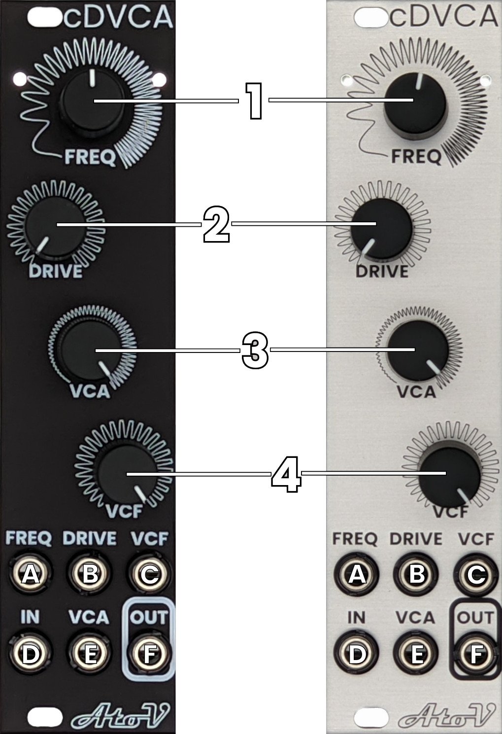
1 - Frequency control
This potentiometer controls the frequency of the carrier oscillator. With nothing in the CV input the range spans from ~4Hz to 34kHz. Lower frequencies can be achieved by sending negative voltage to the FREQ CV input.
The corresponding CV input is mixed with this control.
2 - Drive control
The drive controls the amount of distortion applied to the incoming input. Internally this control the amplitude of the internal oscillator triangle wave, the higher the setting, the lower the amplitude. By comparison this makes the input signal appear louder to the module and therefore the tip of the wave gets clipped. This is because when the input signal is louder than the internal carrier oscillator the module encodes the sound with the maximum PWM value, clipping the signal.
The corresponding CV input is mixed with this control.
3 - VCA control
This control the overall volume. When nothing is connected into the VCA CV input, this is a simple volume control. When CV is used this becomes an attenuator for the incoming CV.
4 - VCF control
This controls the frequency cutoff of the internal 1 pole low pass filter
The corresponding CV input is mixed with this control.
A - Frequency CV input
This input allows to control the internal VCO frequency using CV. The oscillator is tuned to track 1V/oct. One can decrease the frequency of the oscillator under what can be achieved with the potentiometer by sending negative voltage.
B - Drive CV input
This input allows you to control the amount of drive applied to the input signal.
C - VCF CV input
This input allows to control the frequency cutoff of the low pass filter.
D - Input
This is the input of the module. If nothing is connected to this input and you tune the carrier oscillator into the audio range, it becomes audible allowing to use the module as a simple synth voice. Additionally, this input is DC coupled in order to achieve pulse width modulation of the internal oscillator.
E - VCA CV input
This allows you to control the amplitude of the output signal using CV. The VCA is fully open at 5V, to is aimed to allow the VCA to fully open with standard LFOS. Higher voltages will be clipped, this allows you to create ASR from AR envelopes, playing with the VCA attenuator will result in shaping you envelope response.
F - Output
The is the output of the module. This output is DC coupled.
Back side

1 - Eurorack power connector
This eurorack module runs on +/-12V and draws 40mA on the +12V and 40mA on the -12V. Mind the polarity of the connector, -12V (red line) of the included power cable goes to the bottom. Always make sure that the power cable you are using is wired properly and that the red line leads to the -12V rail on you power bus.
Please turn your system off before connecting any new modules.
This module is equipped with reverse polarity protection.
2 - PCB revision number
This is the revision of the PCB of your module. If you one day you need support for your module, please give us this number when contacting us.
3 - Module Serial number
This number is unique to your module. Please give us this number in case you contact us.
We keep track of the history of our modules (date of manufacturing, retailer, any support claim, eventual repairs etc…). If you buy a second hand Atovproject module, do not hesitate contacting us so we can give you the history of your module.
Massive thanks to the beta testers: Marius Krämer, Alexander Biryukov, Francesco Devincenti