
AtoVproject DHO - User Manual
Introduction
The core idea of the DHO was to solve a fundamental issue that complex oscillators usually have. Despite their amazing sonic potential, complex oscillators are very difficult to take full advantage of as they also require a large amount of modulation to give life to the sound they produce. To solve this issue, we designed an analog complex oscillator with internal modulation based on video game algorithms to facilitate this lively sound creation process.
The Dual Harmonic Oscillator, or DHO in short, is a complex oscillator where each of the two oscillators is generating 4 octaves of triangle waves. The mix of these waves is used to modulate the other oscillator using through-zero FM. The two oscillators are then mixed into an analog wavefolder (designed by Befaco).
We then used simplex noise to modulate all the parameters, allowing for 10 parameters to be modulated just using one CV. Additionally, there are also 10 internal LFOs that one could use to control any of the parameters.
This module is, as far as we know, the first Eurorack module featuring haptic feedback. This allows the module to communicate information back to the user in a fashion that we are now all accustomed to by the wide usage of this technology in smartphones.
The inspiration
The DHO features internal modulation based on simplex noise. This parametric noise is most commonly used for map generation in video games. When looking at a topological map in one dimension, the hills and valleys made us realize that it would be a perfect modulation source for synthesizers.
We then got to work to develop this one “inspiration” knob.
At Atov, we are big fans of randomly generated patch systems found on synths like the Waldorf Blofeld, for example. However, these have a major flaw, which is that there isn’t usually an undo button. On the other hand, other instruments like the Intellijel Shapeshifter or the Melbourne Instruments NINA have a great feature that allows interpolation between the values on the front panel and the values stored in a saved preset.
We decided to implement simplex noise as a source of modulation. Applied to one parameter, this noise will offset the set value up or down. Moving through the map, this will cause this value to move up and down in a way that appears random to humans. As we have 10 instances of this noise, the offset value on each parameter is going to be different. This means that if one turns the MOD encoder infinitely, eventually all possible combinations of parameters will be found.
The great thing about this simplex noise is that even if it appears random to a human, it is, in fact, parametric. This means that if the same input values are given to the algorithm, the same output will come out. In the context of the DHO, this means that one can just turn the MOD encoder the opposite way to retrieve the previous results.
Furthermore, as this is a continuous parameter, we could add CV control that allows exploring around the coordinate set by the MOD encoder. This allows modulation of up to 10 parameters using just one CV.
We took the opportunity to make this complex instrument even more usable by implementing LFO modulations. One can apply LFOs instead of an offset. In this case, the simplex noise is controlling the frequency of the LFO. The aim of these LFOs is to give life and movement to an otherwise static tone.
If one desires more specific or more controlled modulation, there are CV inputs and attenuators for all but two parameters.
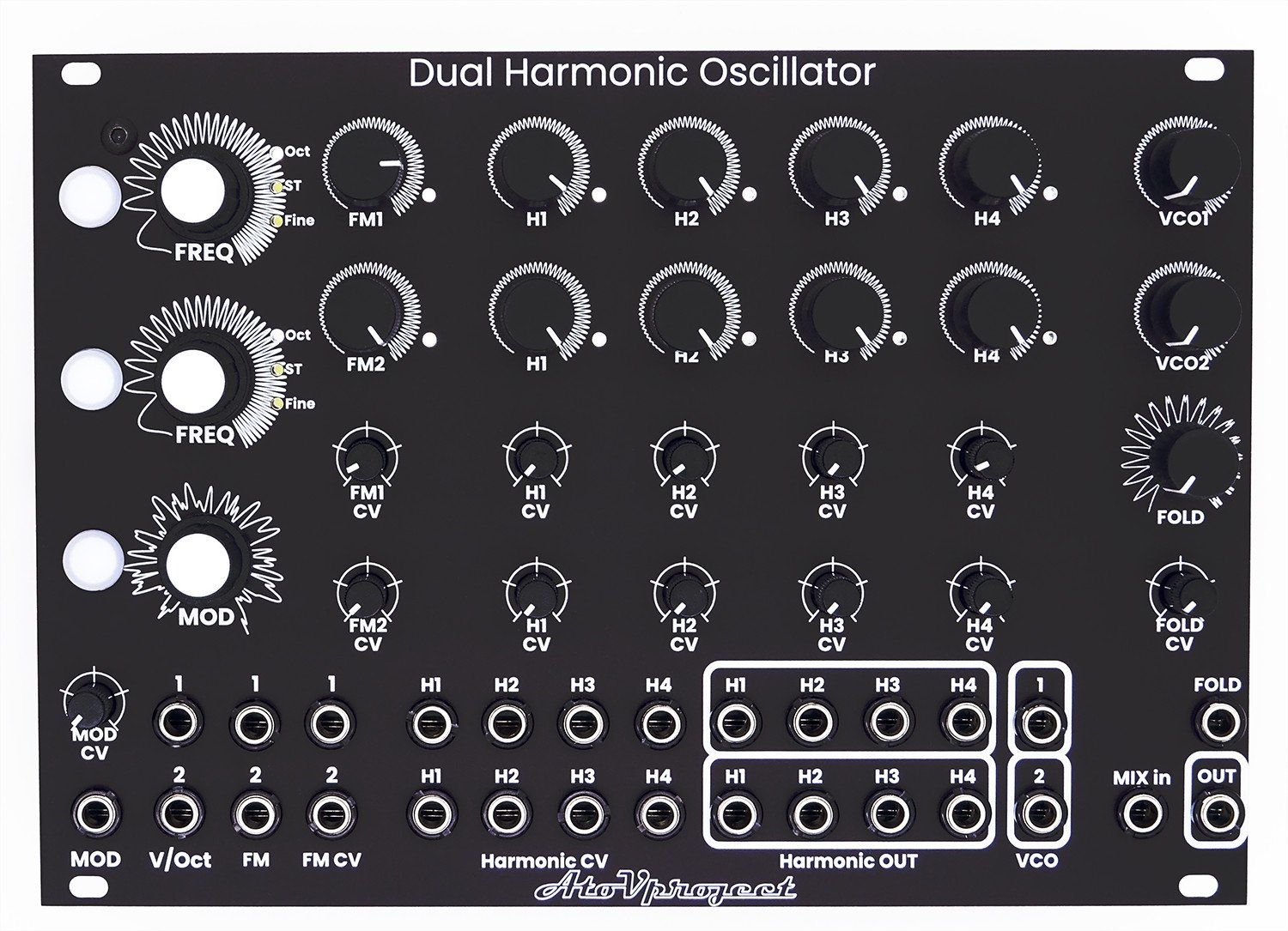
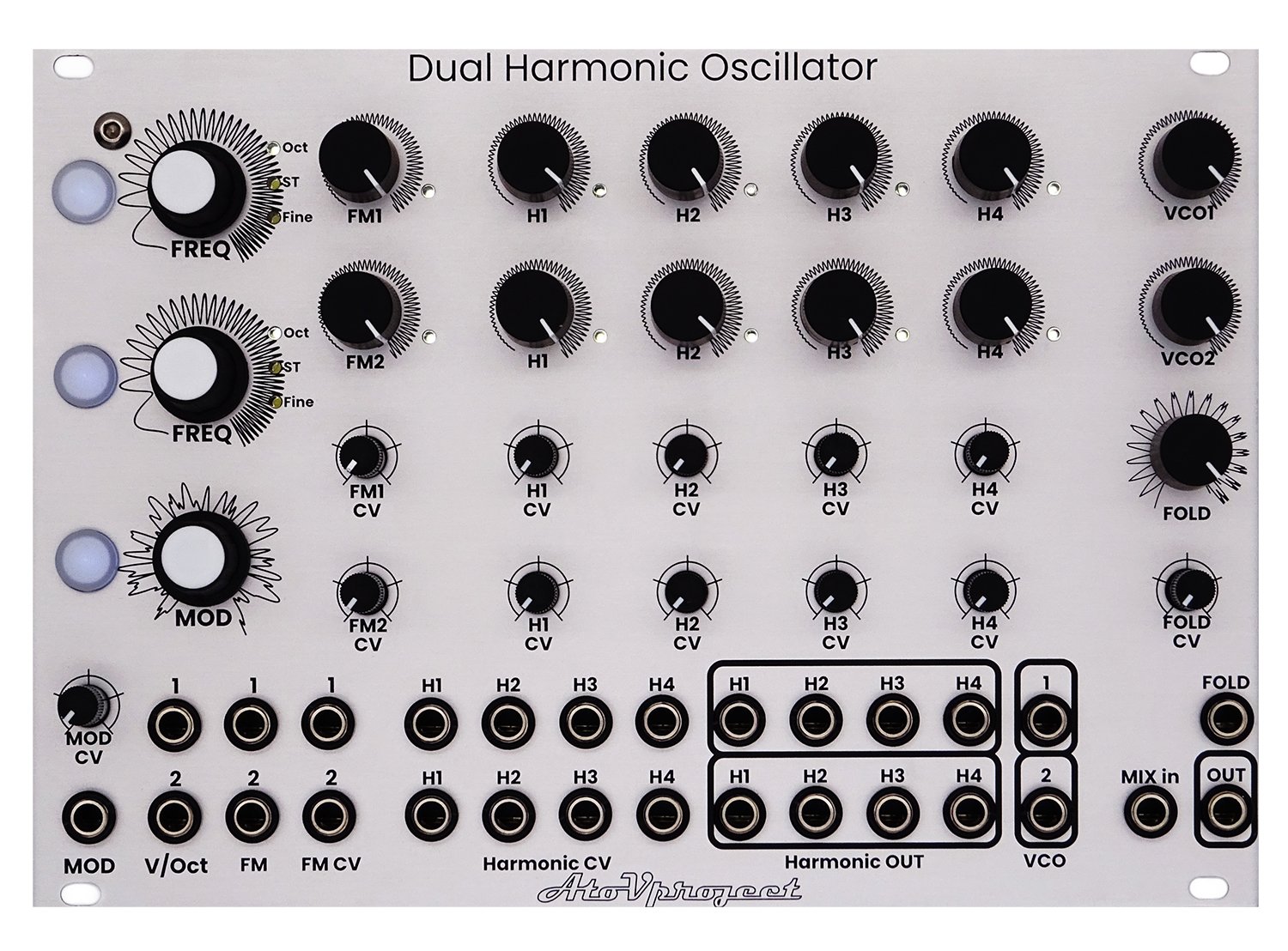
Interface
The DHO features two identical oscillators, and most of the controls are repeated for each oscillator. The controls are organized in rows. The first row of controls is for the parameters of the first oscillator, and the second row is for the second one.
The same thing applies to the CV attenuation section and for the input and output jacks.
The modulation input CV range is +/-5V.
All other CV inputs have a range of 0-5V and have an attenuator to reduce the range of the modulation.
Haptic feedback
The DHO is equipped with a vibration motor that provides haptic feedback for actions performed on the DHO. Please note that the performance of the haptic feedback is strongly dependent on the "mass" it has to move. What this means is that the heavier the case, the less effect will be felt. This can be solved by slightly loosening the screws holding the DHO.
Powering the DHO
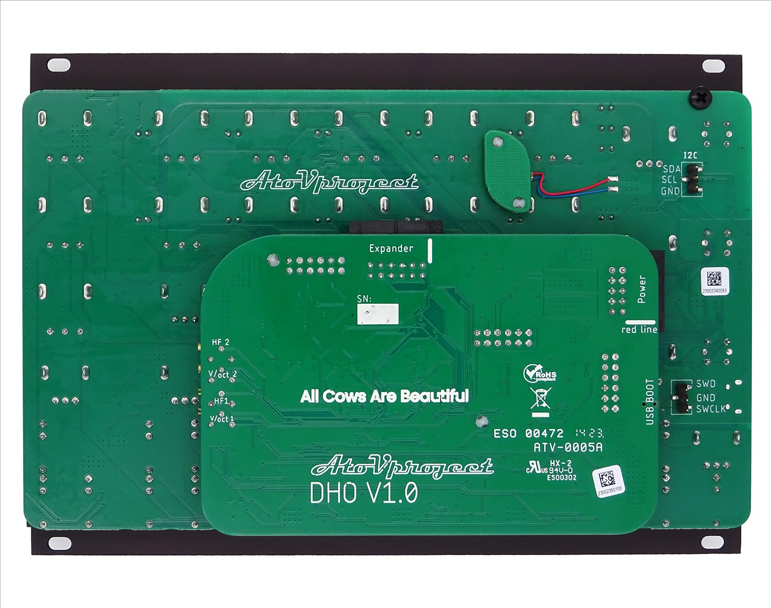
The DHO is powered using a Eurorack power supply and runs on +/-12V. The power connector is shrouded, and the power lines are diode-protected.
Connect the provided 10 to 16-pin ribbon power cable from your Eurorack bus board to the module. In the eventuality that you are not using the provided cable, always make sure that the -12V aligns with the red line on the cable.
Here is a 30 minute video about how to plug your Eurorack module correctly.
The DHO consumes 215 mA at 12V on average and can peak up to 340 mA with haptic feedback. One can deactivate the haptic feedback functionality of the DHO. The steps to achieve that are described in the Config Menu section.
The DHO consumes 140 mA at -12V.
Tuning

As the tuning is digitally controlled, we could implement a few tricks that most oscillators are not capable of.
Two encoders allow tuning up and down the frequency of each oscillator. The tuning resolution can be selected by pressing the tuning resolution buttons to the left of the encoders, and the current state is indicated by the LED to the right of the encoders.
The following resolutions are available:
Octave
Semitone
Fine-tuning
Off (in this mode, the encoder is deactivated)
Tuning modes:
To switch between modes, hold the first tuning resolution button and tap the second one.
Independent tuning: The two oscillators are tuned independently from each other.
In this mode, the LEDs of both tuning resolution buttons are solid.
Linked tuning: The encoder of oscillator 1 controls the tuning of both oscillators, and the encoder of oscillator 2 tunes only the second oscillator.
In this mode, the LED of the first tuning resolution button is solid, and the second one is breathing.
VCO/LFO mode:
The tuning range of the oscillators can be changed by pressing and holding the tuning resolution button and turning the encoder left for LFO range and right for VCO range. The haptic feedback will send a pulse to indicate the operation was successful.
VCO mode: The frequency of the oscillator can be tuned between 20Hz and 1.2kHz. In this state, the LED indicating the tuning resolution on the right of the encoder is solid.
LFO mode: The frequency of the oscillator can be tuned between 27mHz (37 seconds) and 2Hz (0.5s). In this state, the LED indicating the tuning resolution on the right of the encoder is breathing.
External control
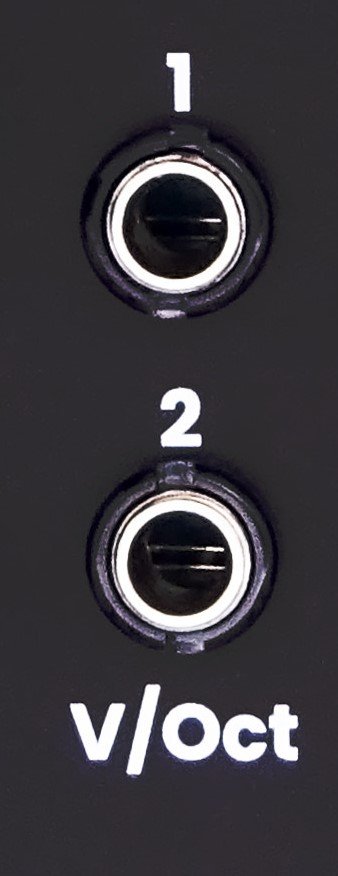
To control the tuning of the oscillators externally, use the V/oct inputs.
The V/oct input for the first oscillator is normalized to the second one, and this connection can be broken by plugging a cable into the V/Oct input of the second oscillator.
These inputs are calibrated to follow the volt per octave Eurorack standards. The frequency of the oscillators doubles for every volt applied to this input.
Sound shaping

Harmonics
The DHO is a so-called harmonic oscillator; each oscillator generates 4 octaves of triangle waves. This means that for each oscillator, the frequency of the second harmonic is twice the frequency of the first one, the third four times the frequency of the first one, and the fourth is eight times the frequency of the first.
The volume of each harmonic is controlled by the H1-4 potentiometer, and the value internally set is represented by the LED to the bottom right of the control.
This setting can also be modulated with external CV using the Harmonics CV (H1-4) inputs. The incoming CV is attenuated by the FM CV potentiometers before being mixed with the internal setting.
The resulting mix of harmonics is then outputted to the corresponding VCO out jacks.
Harmonic outputs
Each harmonic has a direct output. These outputs are pre-VCA and are not affected by the harmonic volume.
Frequency Modulation
The DHO also features through-zero frequency modulation that allows the first oscillator to modulate the second one, and the second modulates the first.
If you want to learn more about the differences between the different types of frequency modulation, I would invite you to read this article from Learning Modular.
We will use the abbreviation FM for the rest of this manual.
The output of VCO 1 is normalized to the FM input 2 of the second oscillator, and VCO 2 is connected to the FM input 1. This connection can be broken by connecting a cable into the FM inputs of the corresponding oscillator.
The amount of FM can be controlled using the corresponding potentiometer (FM1 or FM2), and the value internally set is represented by the LED to the bottom right of the control.
This setting can also be modulated with external CV using the FM CV inputs. The incoming CV is attenuated by the FM CV potentiometers before being mixed with the internal setting.
Internal modulation

One of the very special features of the DHO is its internal modulation system.
We've used simplex noise, an algorithm commonly used in video games and computer graphics that is employed for procedurally generated terrains and textures.
What it means is that one can use this noise to apply an offset to any of the harmonic volume or FM amount. One can then turn the MOD encoder to travel in the map, and the offset of this value will be different. As 10 independent instances of this noise are running in the DHO, the noise value for this noise will be different for all parameters, allowing all possible combinations of parameters.
Additionally, as this is algorithmic and not random, the same input will result in the same outputs, meaning that one can undo their changes by turning the MOD encoder in the other direction.
This can also be controlled using CV using the MOD input and its corresponding attenuator. The input responds to signals from -5V to 5V. This input allows scanning through the simplex noise map around the coordinate set by the MOD encoder.
Assigning modulation
To add modulation to a parameter, one has to enter the modulation page. This is achieved by pressing the MOD button. When on this page, the LED of the MOD button should be lit up. In this page, the LED next to the controls shows the amount of modulation.
On this page, the FM and H1-4 potentiometers allow you to set the amount of modulation for each specific parameter. The LED next to each parameter then indicates the amount of modulation assigned to each parameter.
Modulation type
One can change the type of modulation assigned to these parameters from an offset to an LFO. The frequency of this LFO is controlled by the noise value.
While holding the modulation button, turn the destination control potentiometer (FM1-2 or H1-4) to change whether the noise or LFO modulation is active on this destination. Set it to the left for an offset modulation (LED off) or right for LFO modulation (LED breathing). The haptic feedback will trigger when the modulation type is changing.
Clear all modulations
To clear all modulation by pressing and holding both tuning resolution buttons for 4 seconds. All modulation will be cleared and the current setting of all potentiometers will be applied.
Mixing and Folder section
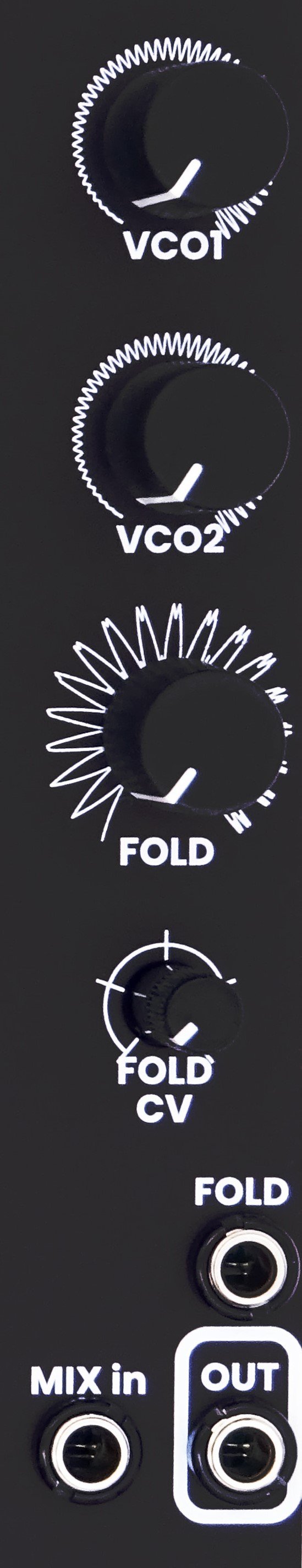
The DHO features a small mixer section and a wavefolder. The two volume potentiometers labeled VCO1 and VCO2 control the volume of each oscillator to be sent to the wavefolder. Please note that the mixer is internally DC coupled. This means that if one of the oscillators is set to LFO mode, this LFO will then control the distortion symmetry of the wavefolder.
External Signal:
One can also use the MIX in input to add a signal into the mixer. This input is DC coupled; therefore, one can use any low-frequency or DC signal to affect the symmetry of the wavefolder.
Wavefolder:
The wavefolder is a four-stage diode based on the circuit B of the Befaco Chopping Kinky with the voltage control section completely modified.
The wavefolder potentiometer is used to control the intensity of the effect. One can use the CV input and its corresponding attenuator to control this effect with CV.
At its minimum setting, the wavefolder has been set up to act as a limiter where all signals under -5V and above +5V will be folded to limit the output range to the Eurorack standard of +/-5V. This means that at full volume with a few harmonics up, the wavefolder will have a minor effect. If one wants to have a purer signal, one should decrease the volume of the VCOs using the volume controls (5) or use the individual VCO outputs (G), use an external mixer and bypass the wavefolder entirely.
Calibration
If the tracking of the DHO is off. On can recalibrate the V/Oct input tracking. There are calibration trimmers on the back of the module allowing to correct the tracking.
We’ve published an online tool to perform the calibration in one pass. Please click this link and follow the instruction in this page. Do this for each oscillator.
Single Pass Oscillator Calibration Tool
After performing this calibration, the internal calibration should be performed again. Please follow the step described in the Config menu - Internal calibration section a bit lower in this page.
Config menu
To enter the configuration menu press and hold the MOD button while turning your system on. The LED of the MOD button will be flashing to indicate that you are in the configuration menu.
Haptic On/Off
Pressing the oscillator 1 tuning resolution button allows you to switch the haptic feedback on (LED on) or off (LED off).
Version check
Pressing the oscillator 2 tuning resolution button allows you to display the firmware version. The current version of the firmware is V1.0
The LEDs should be as such (Blue LED is on, grey are off):
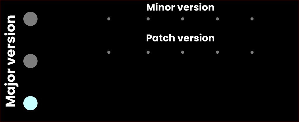
Press the MOD button to get out of the version check page.
Internal calibration
The tuning of the DHO is controlled in a digitally. This mean two digital to analog converter send voltages to each oscillators to offset their frequency. This requires prescise calibration. To simplify this process we have designed an internal calibration system that allow for this step to be automated.
If when you are turning the encoders and the octave shift are not perfect, you might want to recalibrate.
To do so while in the configuration menu, press and hold the two tuning resolution buttons. The LED in these buttons should turn on and the LEDs next to the FM and harmonic volume knobs will turn on one after the other to indicate the progression of the process.
This process takes about 1 minute to complete. At the end of the process the module will restart normal operation.
Exit configuration menu
Press the MOD button to resume normal operations
Firmware update
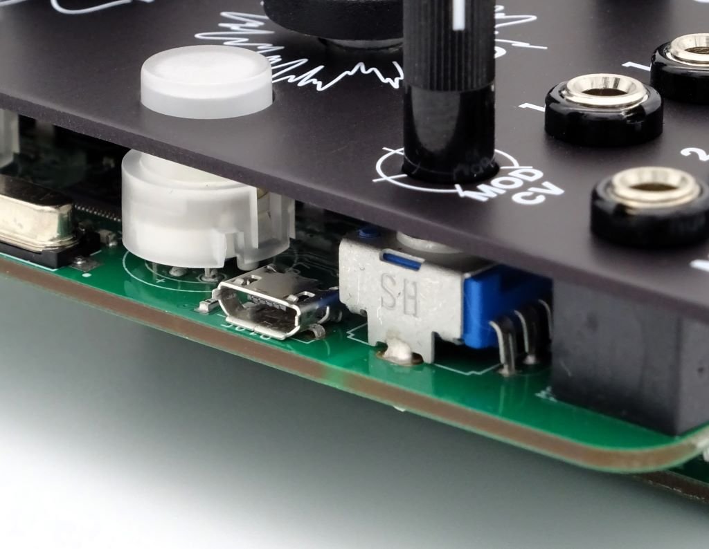
WARNING : the micro-USB connector is fragile please handle it with care.
Start by checking the firmware version of your unit. The procedure to check the firmware is described in the Config Menu section of this manual
The current version is version V1.0
Procedure:
Turn off your Eurorack system
Connect the DHO to a computer using a micro-USB cable.
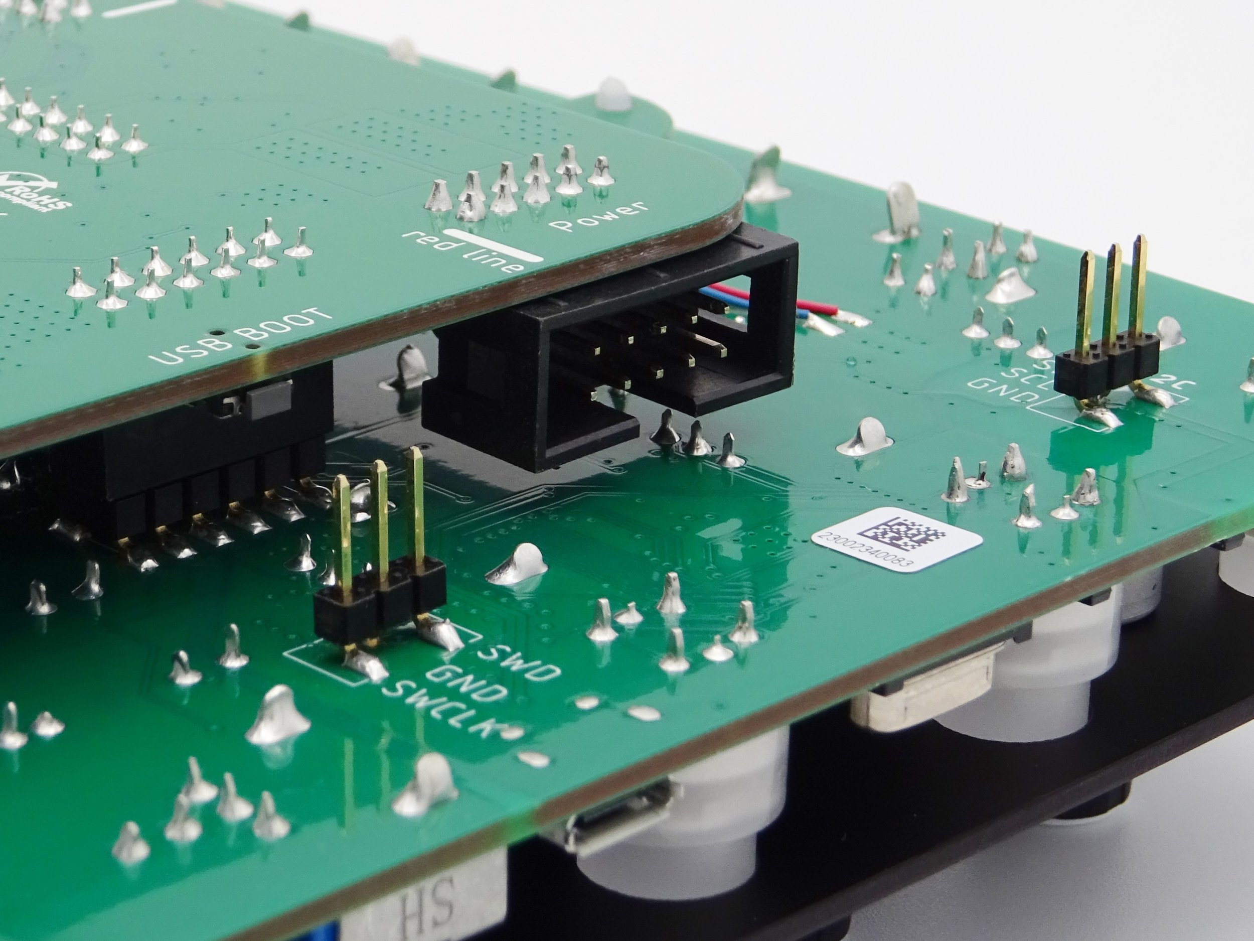
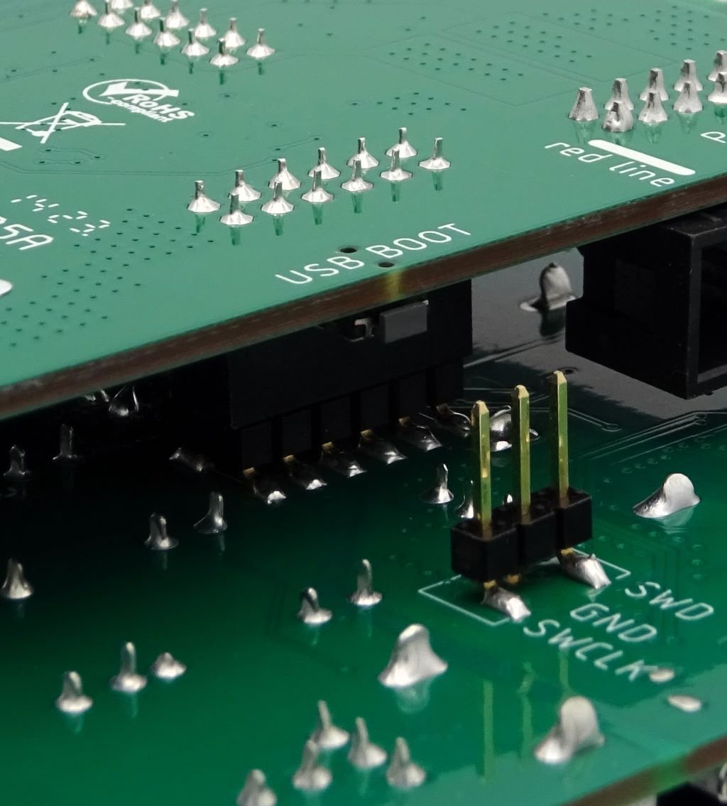
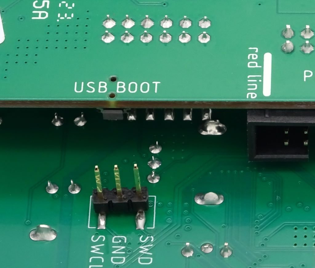
Then power the module while holding the USB BOOT button situated on the edge of the second PCB
The DHO will appear as a storage device named : RPI-RP2.
Drag and drop the firmware file into this storage device
The unit will automatically restart
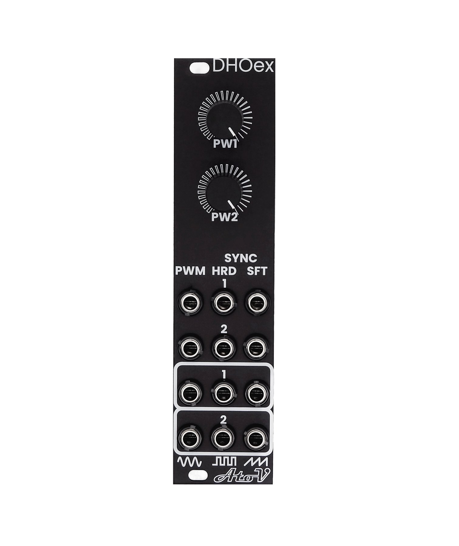
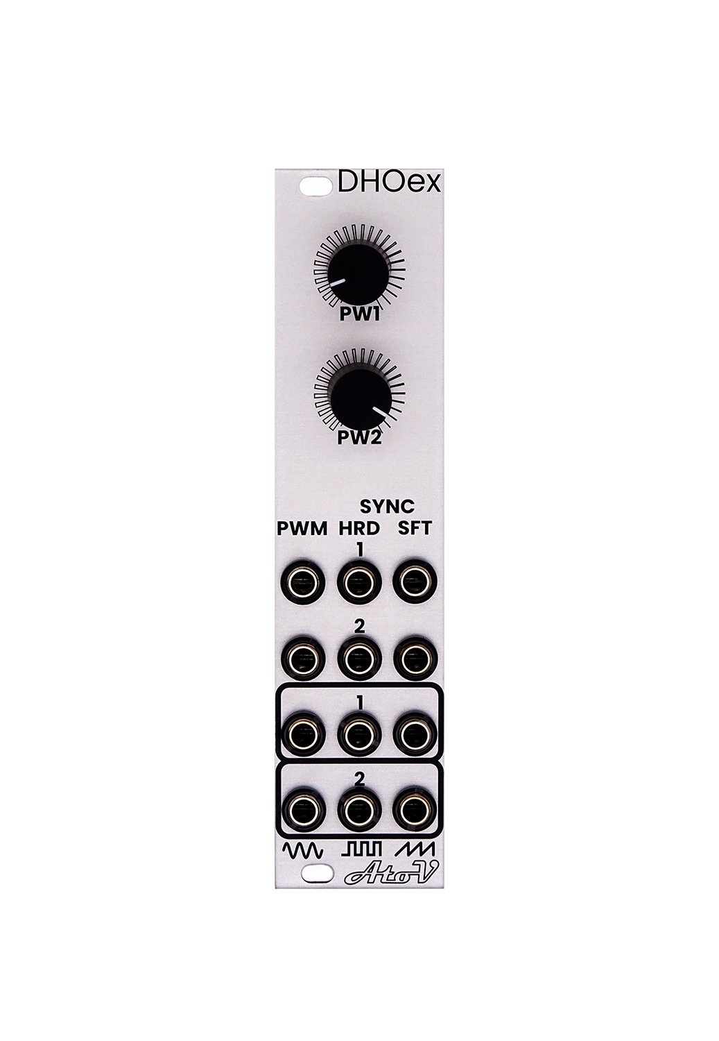
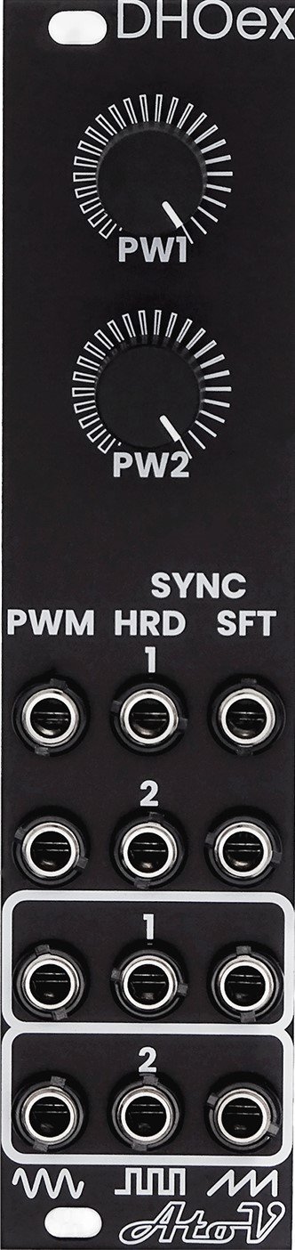
The Expander - DHOex
The DHO ships with its expander (DHOex). This expander is designed to bring more traditional oscillator features to the DHO.
As for the main module the DHOex is also organized by rows of controls that correspond to each oscillators.
Note: All outputs are calibrated to +/-5V signal.
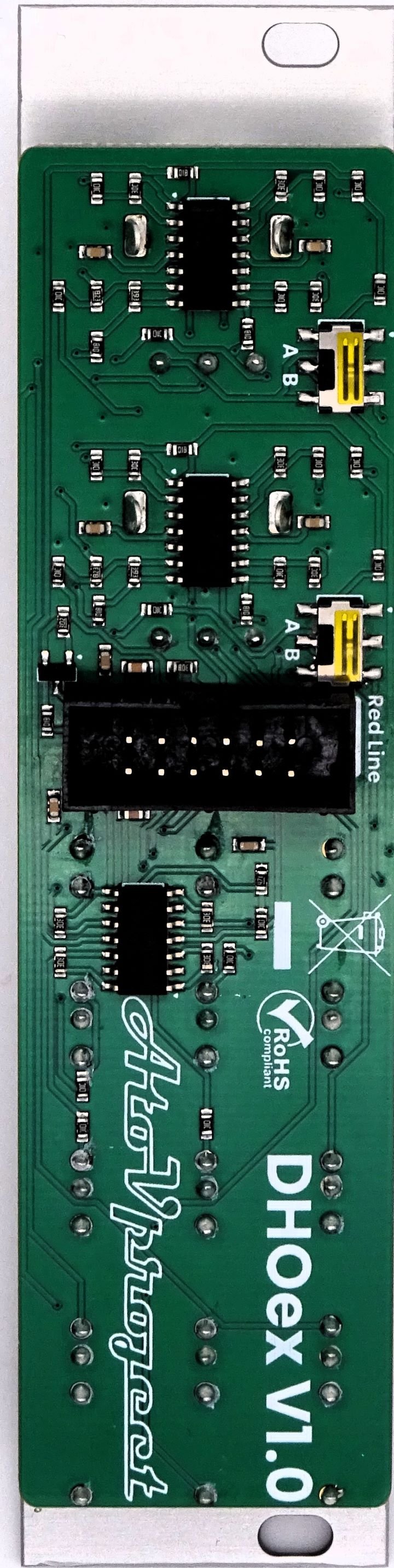
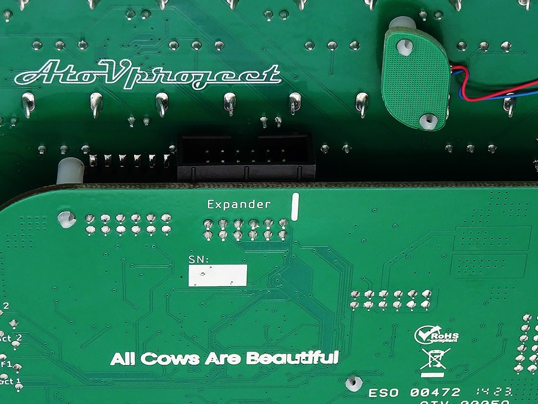
Connecting the DHOex
To connect the DHOex to the DHO, use the provided 12-pin ribbon connector. Please mind the orientation.
Connect both to the connector on the back of the DHOex and to the expander connector on the main module.
SYNC Inputs:
These inputs are the sync inputs for the corresponding oscillator. The DHOex features inputs for both hard (HRD) and soft (SFT) sync. These inputs feature comparators. This was implemented to allow for the use of non-square waves as sync inputs, enabling the use of individual harmonic outs or the VCO outputs, for example.
PWM:
One can modulate the pulse width of the square wave using the PWM CV input. The PW1-2 potentiometers' functions are set by the position of the switch on the back. In position A, the CV is mixed with the potentiometer value. In position B, the CV input is attenuated by the potentiometer. Two switches are available, one per pulse width control, the upper one for the first channel, and the lower one for the second.
As a side note, the PWM on this module features some hysteresis and is derived from the sine wave, as opposed to the triangle or sawtooth as it is in most other synthesizers. This was done this way to give a different flavor to this classic sound.
Waveform Outputs:
These outputs are calibrated to +/-5V and follow the frequency of the base harmonic of each oscillator.
The waveforms available are sine, square with PWM, and sawtooth waves.
Acknowledgement
We would like to express our deepest gratitude and appreciation to all the testers who dedicated their time and expertise to help us refine and improve the DHO.
Your commitment and valuable insights have been hugely important to make the DHO what it is now.
So from the bottom of our hearts, a huge thank you to:
Marius Krämer aka Bassinfected owner of the label Filter Movement and incredibly skilled mixing and mastering engineer. give them some love and a follow on instagram
Steven Williams aka Drusnoise sustainability scientist and live performer. Steve also runs great workshops on how to perform live with music gear and is a great supporter of the live performing electronic musician community in Berlin by running the Berlin Modular Society collective.
Acknowledgment:
We would like to express our deepest gratitude and appreciation to all the testers who dedicated their time and expertise to help us refine and improve the DHO.
Your commitment and valuable insights have been hugely important in making the DHO what it is now.
So, from the bottom of our hearts, a huge thank you to:
Marius Krämer, aka Bassinfected, owner of the label Filter Movement, and an incredibly skilled mixing and mastering engineer. Give them some love and a follow on Instagram.
Steven Williams, aka Drusnoise, a sustainability scientist and live performer. Steve also runs great workshops on how to perform live with music gear and is a great supporter of the live-performing electronic musician community in Berlin by running the Berlin Modular Society collective.