
AtoVproject cLFO - User Manual
Overview
The cLFO is a dual voltage-controlled LFO, and each oscillator features three different waveform outputs: Triangle, Sawtooth, and Square waves. The phase of the Sawtooth on LFO1 and LFO2 is inverted to give different flavors of modulations.
The waveform outputs emit signals between +/- 5V.
The frequency of the LFOs without any CV input ranges from ~2 minutes to 0.05 seconds (10Hz) and can be expanded with CV up to ~400Hz and down to around 13 hours per cycle.
The cLFO features a ring modulator aimed at combining the two LFOs into more complex and evolving modulations. The ring mod effectively creates a related signal from two unrelated LFOs, which is very useful and allows tying multiple voices together by giving them related modulations.
Ring modulators are also called four-quadrant multipliers. This means that they multiply the two input signals, taking into account their polarity (unlike VCAs where the negative part of the CV input is ignored).
The ring modulator has been set to give unity gain at 5V. This means that if you send a 1V signal on one of the inputs and send 5V to the other, the output will be 1V. This ring modulator behaves in a linear fashion.
At the time of the release of the cLFO, we also launched the MM or Matrixable Mixer. This module is a 4-to-1, 4hp CV mixer with 2 attenuators and 2 attenuverters. It is sold as a pair as the main concept is to be able to chain them together. This was developed as a way to expand and combine the functionality of your modulations, thus making it a perfect partner for the cLFO. We’ll describe here a few patches that involve the MM. Of course, any other module with similar functionality would also work without any issues.
More info at: atov.de/mm
Interface
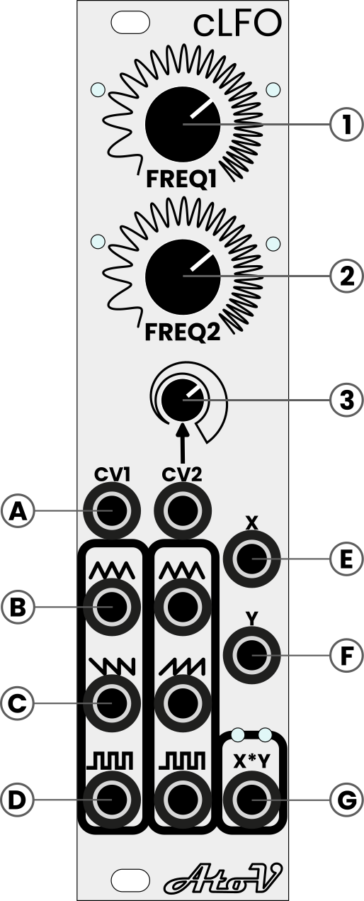
1 & 2 - Frequency controls
These potentiometers control the speed of the LFOs. The upper one controls the first LFO and the lower one controls the second LFO. With nothing in the CV input the range spans from ~2min to 0.05s (10Hz) and the scaling is exponential. Lower and higher frequencies can be achieved by sending voltage to the corresponding CV.
3 - CV2 Attenuator
This potentiometer allows to attenuate the effect of the control voltage applied to the CV2 input.
A - LFO frequency inputs
The jacks on top of the left and middle columns are labelled CV1 and CV2. Sending CV signals to these connectors controls the frequency of the LFO1 and LFO2 respectively. This follows an exponential frequency response, however, it is not calibrated to the V/Oct standard. The triangle output of LFO1 is normalled to the CV2 input and the default connection is broken by connecting a jack into CV2.
B - Triangle wave output
C- Sawtooth wave output
The sawtooth output is a ramp down for LFO1 and a ramp up for LFO2. This was done to add a bit of flexibility and options.
D - Square wave output
E - X input of the ring modulator
The triangle output of LFO1 is normalled to the X input.
F - Y input of the ring modulator
The sawtooth output of LFO2 is normalled to the Y input.
G - X*Y output of the ring modulator
Powering the cLFO
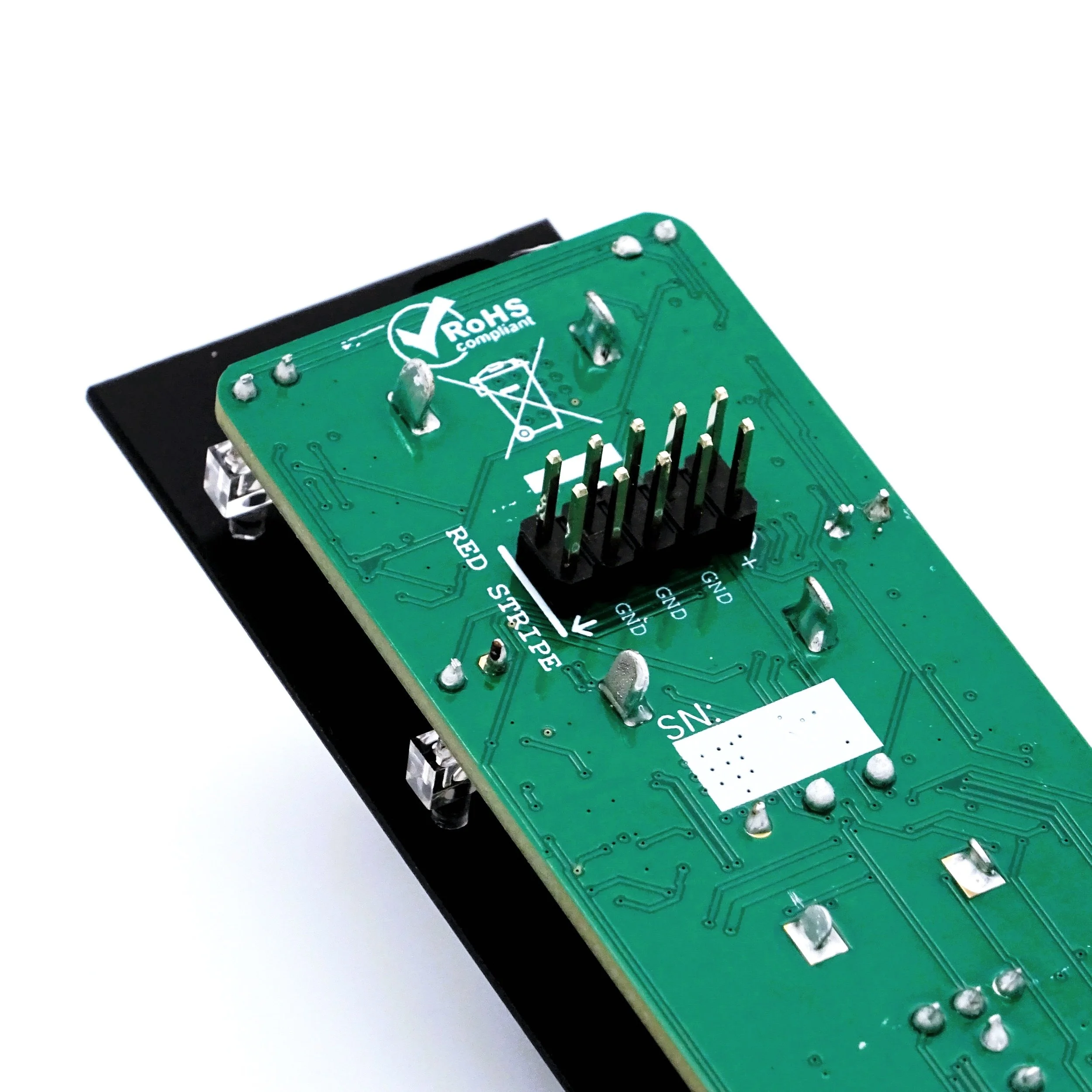
This Eurorack module runs on +/-12V and draws 52mA on the +12V and 60mA on the -12V. Mind the polarity of the connector, -12V. The red line of the included power cable goes to the left. Always make sure that the power cable you are using is wired properly and that the red line leads to the -12V rail on your power bus.
Please turn your system off before connecting any new modules.
This module is equipped with reverse polarity protection.
Patch suggestions
Variable waveform LFO
Using LFO 2, you can create continuously variable waveforms by self-patching one of the waveform back into its own CV input. The CV attenuator then becomes waveform control.
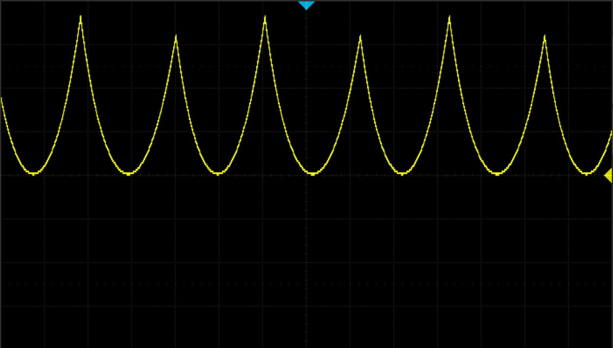
Here are waveform examples captured at maximum feedback:
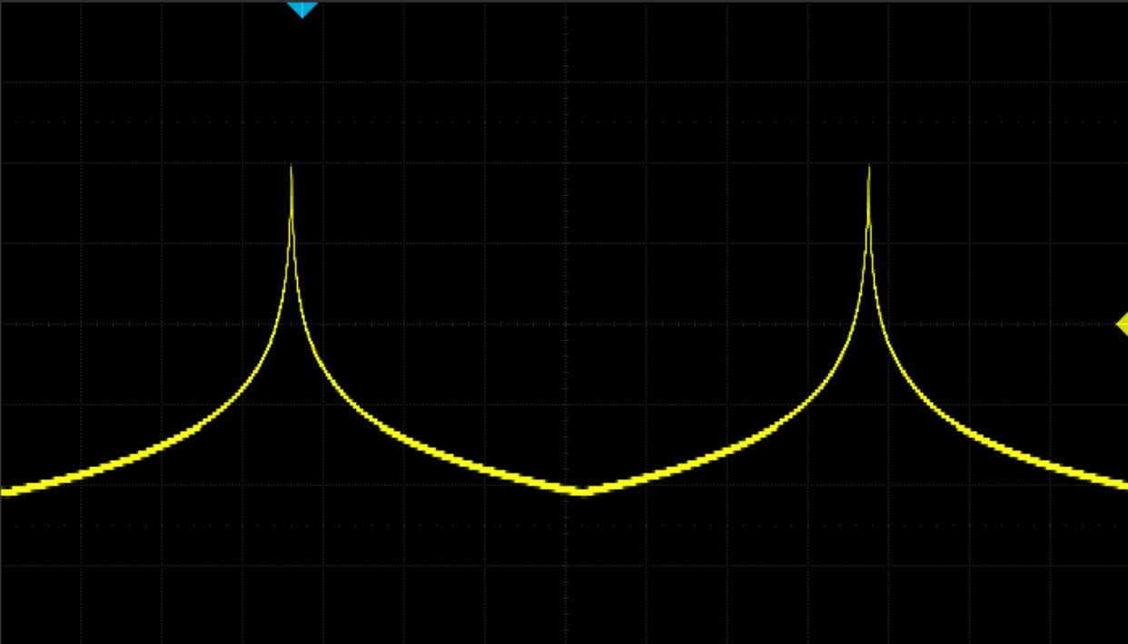
Triangle feedback - Triangle output

Triangle feedback - Sawtooth output
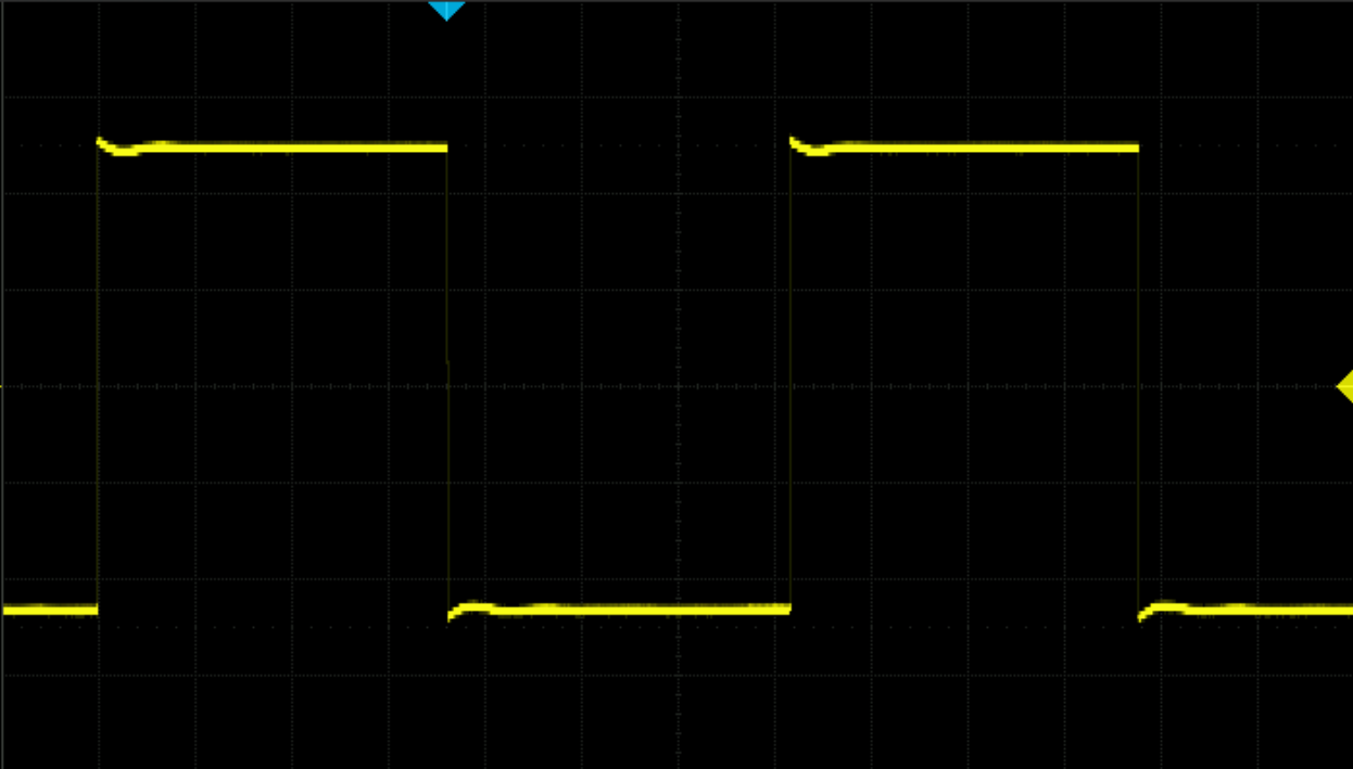
Triangle feedback - Square output

Saw feedback - Triangle output

Saw feedback - Saw output

Saw feedback - Square output

Square feedback - Triangle output

Square feedback - Saw output

Square feedback - Square output
To make this CV controllable, you can use the ring modulator as VCA. Connect one of the LFO waveform outputs into the X input and another slower LFO/envelope/CV into the Y input. Then plug the X*Y output of the ring mod back into the CV of the first LFO.
Note that as this wave-shaping technique is based on exponential frequency modulation, the overall LFO frequency will be affected.
Squared waveforms
By connecting the same waveform into both inputs of the ring modulator, you can create a new set of waveforms by multiplying waveforms by themselves. This gives positive-only waveforms as the square of a (real) number is always positive. This is great way to create pitch bend or vibrato effects sounding like string instruments. When a musician pulls a string they can only add tension to the string and therefore only pitch the note higher. Great results can be achieved here by combining this technique with the delayed LFO effect (using an external VCA).

Audio-rate ring modulation
As the ring modulator on the cLFO is perfectly capable of handling audio signals, you can use it to create the classic Sci-Fi style sounds ring mods are famous for.
Because the cLFO frequency range can be extended using CV, you just need to send some positive CV into both frequency CV inputs to raise the frequency into audio range. Send your waveform of choice into the two inputs of the ring mod and have fun!
If accurate tracking is important, you can also use external VCO instead of the internal ones that are more purposefully built for such tasks.
Super slow LFO
As with the previous example, the frequency of the oscillators of the cLFO can be extended by using external CV. Sending negative CV you can make the LFO run EXTREMLY SLOW, around 13 hours slow.
One trick to make very slow LFOs more interesting is to use some sort of wave-shaping on the output such as wave-folders.
Delayed LFO
This is an effect found on some older Roland poly synths like the Jupiter, Juno and JX series where the LFO effect ramps up after some delay. This can very easily be achieved with the cLFO and a slowly ramping up envelope. Connect the desired LFO waveform into the X input and the envelope into the Y input. In essence, the ring modulator is basically a bipolar VCA. Therefore, when sending a positive only CV like an envelope it will behave like a regular VCA and the LFO effect will increase slowly as the envelope slowly rises.
Freezing
Because of the extended range of the CV inputs on the cLFO, it is possible to create a ”freezing” effect by taking a square wave from LFO2, amplifying it and offsetting negatively with an MM so that the voltage range of this square wave goes from being -5v to +5v to -10v to +0v and patching this to CV1 on cLFO.
This can also be done using gate signals from another module. Plug the gate into channel 3 of an MM, invert the signal and send it into the CV input of one of the LFOs. When the gate goes high then the LFO stops.
You can also invert this effect by keeping the gate signal positive and offset the signal using channel 4. This would cause the signal to be negative when the gate isn’t present stopping the LFO and when the gate goes high the LFO starts again.
LCR synthesis (Left Center Right)
Some of the hardest things to design in a synth are mono-compatible, realistic and lush stereo soundscapes. The cLFO has the potential to be a powerful tool in this regard because it offers both unrelated (LFO1, LFO2) outputs and correlated (X*Y) outputs. We can combine this fact with a classic studio technique “LCR Panning” to create a bubbling, mono-compatible stereo drone.
Using two MMs (or a stereo Mixer), set up three channels so that channel 1 is panned all the way to the Left, channel 2 is panned in the centre and channel 3 is panned to the right.
Using a single oscillator and 2 saturation / wave-folding / wave-shaping modules create a 3-layer voice.
Patch a basic shape from your oscillator into the centre channel, and patch the other two wave-shaped layers into channels left and right channels. Now using VCAs, modulate the amplitude of the waveshapes of the three channels with 3 LFOs from cLFO. We suggest patching X*Y to the VCA on channel 2 on the mixer so that whenever LFO1 and LFO2 are either both positive or both negative the mid channel is audible.
Because all 3 modulation sources are connected to each other by a ring modulator you can go wild and even enter audio-rate modulation and still achieve mono-compatible results.